What is a digger hydraulic cylinder made of | HITE Accessory
Hydraulic cylinders transmission equipment is usually composed of four elements: power, execution, control and assistance. And the digger hydraulic cylinder is used to achieve linear reciprocating motion or less than 360. The hydraulic mechanism of the reciprocating swing motion has a simple structure and reliable operation. It is also the main actuator that is widely used in the hydraulic system. It converts the hydraulic pressure energy generated by the prime mover in the form of mechanical energy to drive the hydraulic pump, and then converts it into a direct drive load. Reciprocating motion or less than 360. An energy conversion device for the mechanical energy of reciprocating swing motion. To understand hydraulic cylinders, we must know the following basic knowledge.
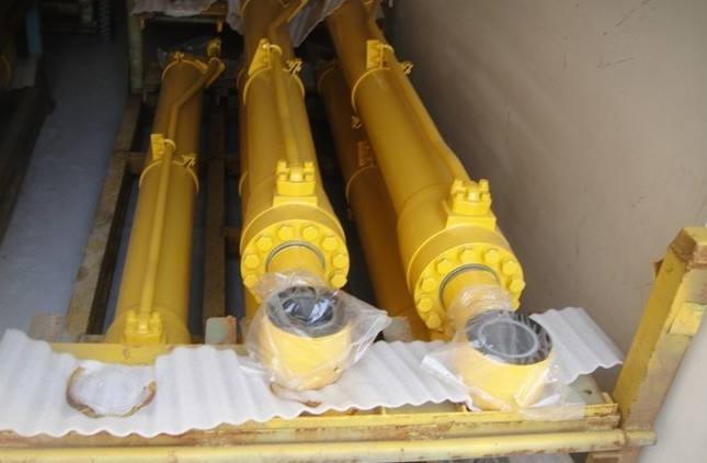
Classification and composition of digger hydraulic cylinder
According to the structure, digger hydraulic cylinders can be divided into four categories: piston cylinders, plunger cylinders, swing cylinders and special cylinders; according to the rated pressure, they are divided into high pressure and ultra-high pressure hydraulic cylinders, medium and high pressure hydraulic cylinders and medium and low pressure hydraulic cylinders.
- Cylinder tube: The cylinder tube is the main part of the digger hydraulic cylinder. It forms a closed cavity with the cylinder head, piston and other parts to push the piston to move. There are 8 types of commonly used cylinder structures, which are usually selected according to the connection form between the cylinder and the end cover. Materials generally require sufficient strength and impact toughness, as well as good welding performance for welding, so commonly used materials are: 25, 45, ZG200~400, 1Cr18Ni9 and so on. Cylinder barrel blanks are mostly cold-drawn or hot-rolled seamless steel pipes, so the process is usually quenching and tempering (to ensure the strength of the cylinder barrel, so that it can withstand oil pressure without deformation and damage) → honing or boring and rolling (to ensure the inner diameter of the cylinder barrel roughness, roundness, cylindricity and straightness, etc., so that the sealing performance of the piston remains unchanged after long-term reciprocating motion) → car (to ensure the design size requirements such as the full length of the cylinder) → drill (to process the oil outlet hole to ensure the entry and exit oil circuit) → pliers.
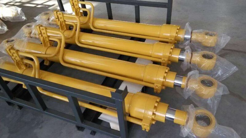
- Cylinder head: The cylinder head is installed at both ends of the digger hydraulic cylinder and forms a tight oil cavity with the cylinder barrel. There are usually various connection methods such as welding, thread, bolt, card key and tie rod, which are generally selected according to the working pressure, the connection method of the cylinder, the use environment and other factors.
- Piston rod: The piston rod is the main component of the digger hydraulic cylinder to transmit force. The material generally chooses medium carbon steel (such as 45# steel). When the oil cylinder is working, the piston rod is subject to thrust, tension or bending moment, etc., it is necessary to ensure its strength; and the piston rod often slides in the guide sleeve, the fit should be appropriate, too tight, the friction force is large, too loose, easy Causing jamming and unilateral wear, which requires appropriate surface roughness, straightness and roundness. Therefore, the process of the piston rod is usually rough turning → quenching and tempering → semi-finishing turning → quenching → pre-plating grinding → chrome plating → post-plating grinding → fine turning.
- Piston: Piston is the main component that converts hydraulic energy into mechanical energy, and its effective working area directly affects the force and movement speed of the hydraulic cylinder. There are various forms of connection between the piston and the piston rod, commonly used are snap ring type, bushing type and nut type. When there is no guide ring, the piston is made of high-strength cast iron HT200~300 or ductile iron; when there is a guide ring, the piston is made of high-quality carbon steel No. 20, No. 35 and No. 45.
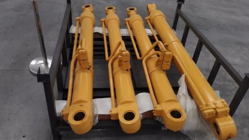
- Guide sleeve: The guide sleeve plays the role of guiding and supporting the piston rod. It requires high matching precision, low friction resistance, good wear resistance, and can withstand the pressure, bending force and impact vibration of the piston rod. A sealing device is installed inside to ensure the sealing of the rod cavity of the cylinder, and a dust ring is installed on the outside to prevent impurities, dust and moisture from being brought to the sealing device and damaging the seal. Metal guide sleeves are generally made of bronze, gray cast iron, ductile iron and oxidized cast iron with low friction coefficient and good wear resistance; non-metal guide sleeves can be made of PTFE and Teflon.
- Buffer device: The piston and piston rod have great momentum when they move under the driving of hydraulic pressure. When they enter the end cover and bottom part of the cylinder, they will cause mechanical collision, resulting in great impact pressure and noise. The use of buffer devices is to avoid such collisions. Its working principle is that the oil (all or part) in the low-pressure chamber of the cylinder can convert kinetic energy into heat energy through throttling, and the heat energy is brought out of the digger hydraulic cylinder by the circulating oil. The structure of the buffer device is divided into two types: constant throttle area buffer device and variable throttle type buffer device.
